Ultrasonic Sprue Cutting, Counting & Cavity Sorting Cells with BRTIRUS0805A: A Sourcing Guide for Injection Molding Buyers


The problem: degating is where molding automation usually stalls
Most injection molding plants automate the press long before they automate what happens after the mold opens. The part comes out, the sprue is still attached, and someone has to cut it, count the parts, and sort them by cavity. That station is where a surprising number of otherwise well-automated plants still run on manual labor — and where quality escapes, miscounts, and mixed-cavity batches originate.
If you are specifying an automated degating cell, the decision is not really "which robot." It is a set of process decisions: how the cut is made, how the cut is verified, how parts are counted, how cavities are tracked, and what the cell must prove before you accept it. This guide walks through those decisions in the order a buyer actually faces them.
Why automate ultrasonic degating and sorting
The value is repeatability, not headcount
Manual degating is a skill. Two operators on two shifts produce two different cut qualities. Ultrasonic cutting is a mechanical process — a sonotrode vibrating at high frequency separates the sprue at the gate with minimal flash and no cutting dust. Once the parameters are set, the cut repeats. That is the actual argument for automation here: the same cut, every cycle, every shift.
Counting and cavity sorting become data, not guesswork
When parts are counted and sorted by a robot, you get a cavity-level record as a by-product. That record is what makes downstream traceability possible — and it is what turns a quality complaint from a plant-wide investigation into a cavity-specific one.
Where automation stops making sense
Automation is not automatically the right answer. Very low volumes, extremely short production runs, or parts with geometry that cannot be presented consistently to a cutting tool may not justify the cell. A useful rule: if the manual station is a bottleneck, a quality risk, or a traceability gap, it is worth evaluating. If it is none of those, it probably is not.
Solution logic: what an ultrasonic degating cell actually contains
A degating, counting, and sorting cell is a system, not a robot. Typical architecture:
| Subsystem | Function | What the buyer must specify |
|---|---|---|
| Robot | Part pick, transfer between stations, placement into sorting lanes | Payload, reach, repeatability, mounting envelope |
| End-of-arm tooling | Grips the runner or the part; presentation to the cutting tool | Part geometry, grip method (vacuum / mechanical), grip repeatability |
| Ultrasonic cutting unit | Separates sprue from part at the gate | Horn geometry, frequency, amplitude, cut force, fixture design |
| Fixture / nest | Holds the part or runner rigidly during the cut | Part-specific; determines cut quality more than the robot does |
| Vision (optional) | Verifies cut quality, confirms presence, reads cavity position | Camera resolution, lighting, cycle-time budget |
| Counting / sorting logic | Tracks parts per cavity, routes to correct lane | How cavities are identified (fixed nest position vs. vision) |
| Controls integration | Sequences robot, cutter, vision, conveyor | PLC brand, communication protocol, safety architecture |
The integration point is the hard part. A robot with good repeatability and a good ultrasonic cutter will still produce bad parts if the fixture does not present the gate consistently. This is where the cell design — not the component list — determines whether the project works.
Key selection factors
1. Payload and reach — sized to the tooling, not the part
The part is usually light. The end-of-arm tooling, the runner, and the dynamic loads during a fast transfer are what consume payload. A 5 kg payload class robot is a common fit for degating cells where the EOAT is a compact gripper and the part is small.
Reach determines whether one robot can serve the press, the cutter, and the sorting lanes without a linear axis. A working radius around 990 mm covers many single-press degating layouts; multi-press or long sorting conveyors usually push you to a larger model or a rail.
2. Repeatability — and why it matters more here than in pick-and-place
Ultrasonic cutting is a contact process. The gate must meet the horn in the same position every cycle, or cut quality drifts. Positional repeatability in the ±0.05 mm class gives the fixture design room to work. If the robot is less repeatable, the fixture must compensate — which usually means a more complex, more part-specific nest.
3. Cycle time — decompose it before you quote it
Do not specify a single cell cycle time. Decompose it:
| Cycle segment | Typical constraint |
|---|---|
| Pick from mold / conveyor | Robot speed, gripper actuation |
| Transfer to cutting station | Robot path, safety envelope |
| Ultrasonic cut | Cut time is a process parameter, not a robot parameter |
| Cut verification (if used) | Camera exposure + processing |
| Transfer to sorting lane | Robot path |
| Placement | Lane geometry, part orientation |
Cut time is often the bottleneck, not the robot. Buyers who specify "the robot must do X cycles per minute" without breaking out the cut time frequently end up with a cell that meets the robot spec and misses the production target.
4. Degating quality checks
Define what "good cut" means before the cell is built. Typical acceptance criteria:
- Gate residue height — maximum acceptable stub, measured on a sample
- Flash — no flash beyond a defined limit
- Part marking — no sonotrode witness marks on cosmetic surfaces
- Runner integrity — the runner must remain intact if it is reground
- Cut consistency — the same criteria across a defined sample size, across cavities
If vision verification is used, the vision system must be specified against these criteria, not against "detects the part."
5. Cavity-level counting and sorting
Two architectures are common:
- Fixed-position sorting: the robot places parts from a known cavity into a known lane. Counting is by cycle. Simple, fast, but requires the mold-to-robot relationship to be deterministic.
- Vision-based cavity identification: the vision system identifies the cavity, and the robot routes accordingly. More flexible, but adds cycle time and a vision-stability requirement.
Whichever you choose, the acceptance test should include a deliberate mixed-cavity run to confirm the cell sorts correctly when cavities are presented out of order.
6. Controls and communication
The robot controller must talk to the ultrasonic generator, the vision system, and the plant PLC. Specify the protocol on both sides before purchase — Ethernet/IP, PROFINET, and Modbus TCP are common; the specific option depends on the controller configuration. If your plant standard is a particular PLC brand, state it in the specification.
7. Environment and compliance
- Cleanroom or controlled environment: ultrasonic cutting generates minimal dust, but the robot's ingress protection rating and lubrication must match the room class.
- Certification: for CE markets, confirm the machine conformity route. The BRTIRUS0805A platform carries CE conformity verification (2006/42/EC machinery, 2014/35/EU low voltage).
- Explosion-proof: not applicable to standard molding cells; if your process involves solvent vapors, verify the specific model's rating rather than assuming.
8. After-sales and integration support
The cell will need fixture maintenance, horn replacement, and re-teaching after mold changes. Ask who supports what: the robot supplier, the ultrasonic supplier, or the integrator. In a degating cell, the answer is usually "the integrator" — which is the argument for buying the cell as an integrated system rather than as separate components.
A reference platform: BRTIRUS0805A
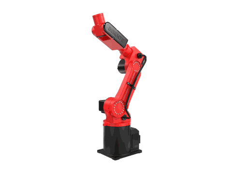
For single-press degating cells with compact tooling, the BRTIRUS0805A six-axis robot is a commonly considered platform. Its published specifications:
| Parameter | Value |
|---|---|
| Type | Six-axis robot |
| Payload | 5 kg |
| Working radius | 990 mm |
| Repeatability | ±0.05 mm |
| Weight | approx. 53 kg |
| Power capacity | 3.67 kVA |
| CE conformity | Yes (2006/42/EC, 2014/35/EU) |
| Explosion-proof | No |
These are platform specifications from the manufacturer's selection catalog. Whether the model fits a specific degating cell depends on the EOAT weight, the number of sorting lanes, and the cut cycle — all of which are cell-design decisions.
Note on scope: YGT Robot (Guangdong Yigaite Intelligent Technology Co., Ltd.) integrates robotic platforms including the BRTIRUS0805A into application solutions. Robot model specifications are published by the robot manufacturer; YGT's role is system integration, application engineering, and on-site delivery.
What to put in your specification document
A specification that gets useful quotes includes:
- Part and runner data: geometry, weight, gate type, material
- Cavity count and layout: how many cavities, and how they are presented
- Required cell cycle time, broken into segments (see above)
- Degating quality criteria, with measurable limits
- Counting and sorting requirements: lanes, traceability output format
- Controls standard: PLC brand, required protocols
- Environment: room class, temperature, existing conveyor interface
- Acceptance test definition: sample size, mixed-cavity run, quality criteria
- Support expectations: fixture maintenance, horn replacement, mold-change re-teaching
Buyers who include item 8 in the specification usually get fewer surprises at FAT.
FAQ
Q: Can a 5 kg payload robot handle a degating cell? A: Usually yes for small-to-medium parts, because the payload calculation includes the end-of-arm tooling, not just the part. The EOAT weight and dynamic loads during transfer are the deciding factors. If the cell needs a heavy gripper or a long arm extension, a larger payload class is the safer choice.
Q: Is vision required for cavity sorting? A: Not necessarily. If the mold-to-robot relationship is deterministic — the robot always picks from a known position — fixed-position sorting is simpler and faster. Vision adds flexibility when cavity presentation varies, but it also adds cycle time and a stability requirement that must be specified and tested.
Q: How do I set a cycle-time target? A: Decompose it. Measure or estimate the cut time first, because ultrasonic cut time is a process parameter and often the bottleneck. Then add pick, transfer, verification, and placement times. A cell specified against a single aggregate number tends to miss the production target even when the robot meets its spec.
Q: What degating quality criteria should be in the acceptance test? A: At minimum: maximum gate residue height, flash limits, no cosmetic marking on visible surfaces, runner integrity if the runner is reground, and consistency across a defined sample size covering all cavities.
Q: Does the robot need to be explosion-proof for a molding cell? A: Standard injection molding cells do not require explosion-proof equipment. If your process involves solvent vapors or a classified area, verify the specific model's rating rather than assuming — explosion-proof is a model-specific option, not a general capability.
Q: Who integrates the robot, cutter, and vision system? A: In most degating cells, an integrator does. The robot, ultrasonic generator, and vision system come from different suppliers, and the fixture design that ties them together is cell-specific. Buying the cell as an integrated system rather than as separate components is usually the lower-risk route.
Q: What communication protocols are available? A: Common industrial protocols include Ethernet/IP, PROFINET, and Modbus TCP. The specific options depend on the robot controller configuration and the plant PLC standard. State your required protocol in the specification so it can be confirmed against the controller before purchase.
Related products
- BRTIRUS0805A six-axis robot — 5 kg payload, 990 mm working radius, ±0.05 mm repeatability
Next step
If you are evaluating a degating, counting, and sorting cell, the most useful first conversation is not about the robot — it is about your part, your cavity layout, and your cut quality criteria. Those three inputs determine the fixture, the cycle time, and the acceptance test.
Send us your part drawing, cavity count, and target cycle time, and our engineering team will review the cell architecture with you — including which platform class fits, how the cut station should be fixtured, and what the acceptance test should cover.
Author: YGT Engineering Team · Guangdong Yigaite Intelligent Technology Co., Ltd. (YGT Robot) · ygtrobot.com